Monday, March 29, 2010

The Vegetable Garden - Part 2

This past Saturday I took advantage of a break in the rain to finish the vegetable garden border. I had already sized everything up and just needed to cut and fasten all the cedar pieces together. Due to the grade of the garden, the front and right side of the border would be 2 layers and the rest single layer.


I assembled the border upside down making it easier to square and ensure it was flat. This also allowed me to nail the bottom pieces into the tops from the underside, and have no nail heads showing from the top.


Once finished I flipped the whole 24'x4' assembly over a contemplated how to move it over to the garden area.


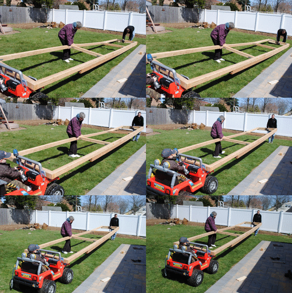
I considered dragging it by myself, but instead called upon the help of Lucas, my 3 year old son, and his battery powered 4x4 Jeep (the one that the border was intended to guard against). I first placed one end of the assembly on the front of his jeep.


With my Mother-in-Law in the middle for extra support, I lifted the far end and Lucas drove towards the garden.


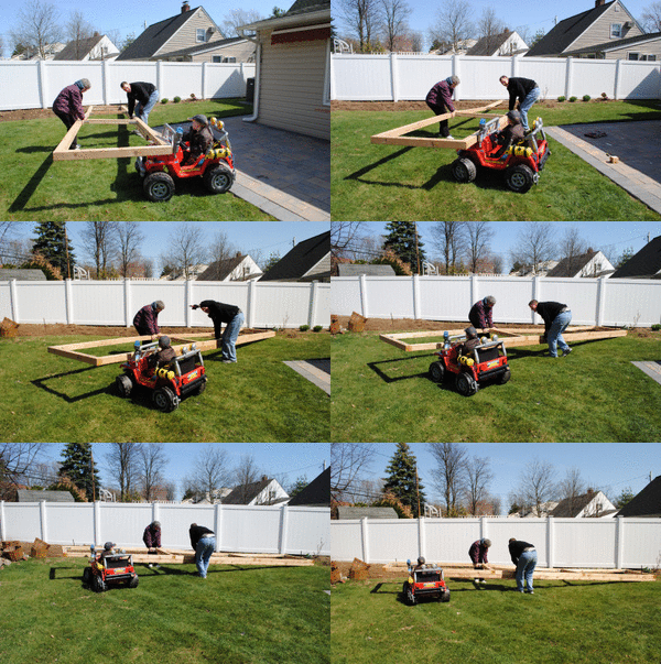
Next we turned the jeep and used it to rotated the assembly 90 degrees into place. It was absolutely hilarious to see Lucas' serious expression as he performed this critical maneuver.


Once in place Lucas backed his jeep into the shed and walk off to the house, satisfied with his accomplishments after a long day at the construction site. All kidding aside, I could never have moved it as easily without him.

The final step was to prop the border up, and dig a channel out so I could easily level it once in place.


With the channels dug, I laid the assembly back down and packed soil under each section to make everything level, using a spirit level of course.


The next step will be to add some compost and top soil as needed and start planting.

The Vegetable Garden - Part 1

We finally had beautiful weather two weekends ago, and so I decided to start work on a vegetable garden. It also helped that our friends Steve & Alex and their son Edwin were staying for the weekend, and Steve was all about renting a tiller.

Our back yard is 60' wide and about 50' deep. We decided that a 24'x4' bed, divided into three 8' sections would suit us best. The land where we live used to be cabbage, cucumber and potato farms, so the ground is really good for growing, though slightly acidic. We started by marking out where we wanted the vegetable garden to be. I decided to dig out the boarder along the grass with a flat shovel to keep a clean edge and avoid tearing up the good grass.


Steve and I drove to Home Depot and rented the biggest tiller they had, an 8 HP, 242cc, 270 lb, Honda Rear-Tine tiller, which just fit int he back of our Jeep Cherokee (with the back door open). Though we tied it in with rope, the Home Depot guy put the tiller in neutral before turning it off, and so as we drove away the thing decided it wanted to stay behind and almost rolled out the back. Steve quickly grabbed it and after putting it in gear, we were homeward bound.


Steve and I fought over, that is, took turns with the tiller and dug as deep as we could along the side fence where I wanted our vegetable garden to be. Since we had the tiller for 24 hours, I decided we may as well till along the the entire back fence and the far corner of our yard which usually grows into a tangle of unkept weeds over the summer. Our eventual goal is to make the corner a nice sitting area, with butterfly bushes and flower, and to plant fruit trees along the back fence, but for now we'll settle just tilled.


The only snag we hit (literally) was a large buried root from an old tree that had come down years before. It took Steve and I about an hour with a hatchet and a couple saws to get the 12" diameter beast out. It nearly broke us, but in the end we prevailed.


With the 24 hour rental up, I took the tiller back to Home Depot on Sunday and shed a few tears. That was one of the coolest machines I had ever used. It was so easy to use and required no effort to turn the ground. Maybe I'll buy one if I get a couple grand to spare.

While we weren't making a raised bed, I did want a border around the garden, to prevent anyone from accidentally driving a battery powered Jeep into garden. I picked up a bunch of cedar 4x4's along with L brackets, deck screws and a dozen 6" nails. While pressure treated wood is much cheaper and I know that it isn't treated with arsenic anymore, I just felt cedar was the better way to go. It looks better and there is that piece of mind that it is untreated.

I started to lay out the pieces to help decide how I was going to frame in the beds but soon decided to call it quits for the weekend. We had done a lot of work and I was really pleased with the results. The border would have to wait for another weekend.


A big thanks to Steve for all his help.

Thursday, March 11, 2010

TV Lift IR Receiver/Controller

Now that I have this awesome motorized TV lift in my bedroom, I wanted to enjoy it in as lazy a fashion as possible. So I needed to go about making an IR receiver/relay switch. The lift is controlled by a wired controller which consists of a pair of switches wired such that pressing one raises the TV and pressing the other lowers the TV.

I needed to replace these switches with Single Pole Dual Throw (SPDT) Relays that were rated for 24VDC and 3 amps (max current at 200 lb, but at 20 lb about 1 amp). I would also need to have an IR receiver that would control the two relays.

I started out with a Velleman MK161 2-Channel IR Remote Receiver Kit.
The downside of this kit is that the control chip that decodes the IR signal and controls the relays only works with Velleman remotes, and I wanted to use my cable remote (for all the DVR features). The includes relays were also only SPST, but they could easily be replaced.

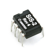
I then came across a chip made by SIMEREC, the SIS-2, which is a 2 Output, Universal IR Remote Control Receiver switch.

My goal was to replace the Velleman chip with this one so it could be programmed to work with any remote control. Unfortunately, the pin outs on the SIS-2 were different from that on the Velleman, so it wasn't a simple swap. I remapped the pins using an IC PC Board from Radioshack and wired this into the MK161 board. I had to make a few other routing changes to the board as the Velleman chip needed a load to go into programming mode, whereas the SIS-2 needed to be grounded.

For the IR sensor, I went with a Vishay TSOP1140 from Mouser, since I was certain it would work with my cable remote. I used 6' of phone line to wire the sensor to the board, so I could put the control box under the dresser and have the sensor just in view on top of the cable box.

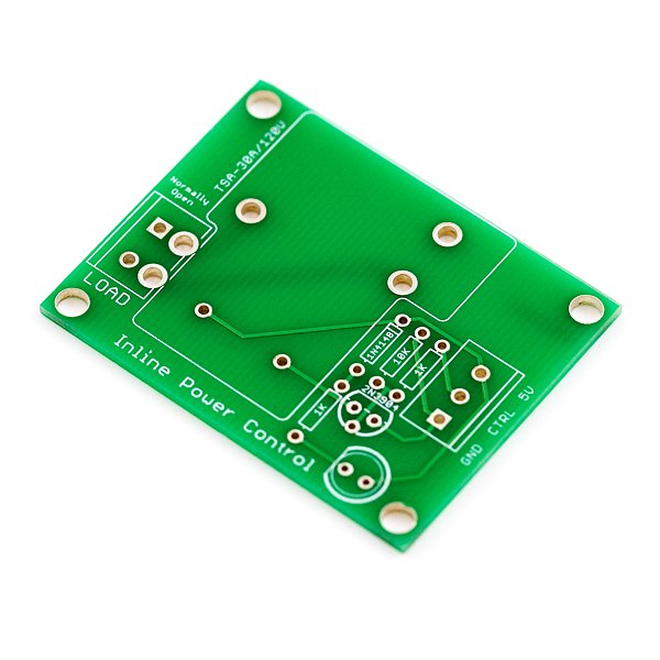
Lastly I decided to use 2 premade Relay Control PCBs from Sparkfun, instead of the mini relays in the MK161 kit. I had to mod the Relay Control PCBs to work with SPDT, but that only required some additional wiring.

I threw everything into a 5x2.5x2"project enclosure from Radio Shack and spliced the new control box into the wired controller cable. I decided to program the Picture-in-Picture channel up/down buttons as the up/down controls for the TV lift. I figured I would use PIP on a 26" TV anyway. After fixing a couple lousy solder joints, everything worked as planned. I can now turn on/off, raise/lower and watch TV without leaving the bed!

I might replace the hacked 4 board solution, with a single PCB that I design using CadSoft Eagle. I can get the board built for about $30 from BatchPCB.

Below is the schematic.


PCB design.


Materials:
  • PCB (BatchPCB #N/A; $30)
  • Programmable IR Receiver SIS-2 (SparkFun ##SEN-08753; $9.95)
  • DC Barrel Power Jack/Connector (SparkFun #PRT-00119; $1.25)
  • Mini Push Button Switch (SparkFun #COM-00097; $0.35)
  • Wall Adapter Power Supply - 12VDC 600mA (SparkFun #TOL-09442; $5.95)
  • IC Socket (Mouser #571-2-1571552-2; $0.80)
  • TSOP1140 IR Receiver (Mouser #782-TSOP1140; $1.11)
  • (2) SPDT Relays (5VDC 20A) (Mouser #655-T90S5D12-5; $2.49)
  • 4 Point Terminal Block (3.5mm) (Mouser #651-1990753; $1.77)
  • Voltage Regulator (UA78L05) (Mouser #UA78L05CLP; $0.52)
  • Diode (1N4007) (Mouser # 512-1N4007; $0.06)
  • (2) Diodes (1N4148) (Mouser #512-1N4148; $0.03)
  • Electrolytic Capacitor (100 uF) (Mouser # 647-UES1H101MHM ; $0.89)
  • Multilayer Ceramic Capacitor (100 uF) (Mouser # 594-A104K15X7RF5UAA; $0.08)
  • Multilayer Ceramic Capacitor (0.1 uF) (Mouser # 80-C330C104M5U; $0.30)
  • Electrolytic Capacitor (4.7 uF) (Mouser #647-UVZ1V4R7MDD1TD; $0.07)
  • (2) LEDs (Mouser # 859-LTL-307E; $0.10)
  • (2) Bipolar Transistors (2N2222A) (Mouser #610-2N2222A; $0.79)
  • Resistor (100 Ohm) (Mouser # 291-100-RC; $0.10)
  • (2) Resistors (220 Ohm) (Mouser #291-220-RC; $0.10)
  • (2) Resistors (4.7K Ohm) (Mouser # 294-4.7K-RC; $0.18)
  • Project Enclosure (5x2.5x2") (Radio Shack #270-1803; $3.69)
Total cost ~$65

Lastly just wanted to say thanks to the tech at Firgelli. He was extremely helpful in determining how to wire up the controller.

My TV Lift

Last fall, after holding off for a long time, my wife and I agreed we should get a TV for our bedroom. Neither of us were too keen on the aesthetics of a TV and cable box sitting on the dresser or mounted to the wall, so I started thinking of ways to hide the TV. To be safe we bought a 26" LCD (Vizio VL260M) that could, if necessary, be mounted to the wall just above the mirror.

Here's our bedroom with the TV sitting on the dresser.


My idea was to mount the TV to the wall behind the mirror, and mechanically raise the TV up above the mirror when we wanted to watch it. The gap between the top of the mirror was ~17" and the TV was 16.8" high, perfect!

At first I looked into ready built powered TV lifts. Only one seemed viable, made by Firgelli Automation.


However, at $600+ it was twice the cost of the TV and not feasible.

My next idea was a pure mechanical lift. My sister-in-law's husband and I spent the better part of Thanksgiving day brainstorming ways to accomplish this (which didn't go over well with my wife and sister-in-law). We considered pulleys, springs, gas pistons, and I finally settled on a parallel arm system, similar to those used for large binoculars mounts or steady cams.


This would allow the TV to freely move up and down without rotating or hitting the wall, and when balanced would require minimal effort to raise and lower. However, after some calculations of the available space behind the mirror, and the weight of the TV being about 20 lb, I would need to have 40-50 lb of counterweight which was unreasonable.

So I went back to the idea of a powered lift. After all, how cool would it be to just lay in bed and hit a button on the remote to raise the TV. Firgelli Automation also produces lift actuators, and sells a nice liner track actuator kit, complete with controller (though unfortunately it's wired).


The FA-200-TR-24-20" looked to work best as it had a 20" stroke, a 200 lb force, and moved at 1"/sec fully loaded.

My plan was to mount the TV to wall to on sliders that allowed it to move up and down. The actuator would be mounted the wall below the TV and I'd connect the TV to the shuttle by an arm. Then as shuttle moved up, this would raise the TV over the mirror, and when the shuttle moved down, the TV would drop too.

To mount the TV to the wall I bought two heavy duty drawer slides from Lowes. I chose ones with 22" of travel so that the actuator would determine the actual range of motion, and the TV wouldn't max out at the top or bottom. These were mounted flat on the wall directly into studs using lag bolts. Fortunately the studs were in a location that allowed the TV to be almost dead center between the two slides.


Next came the task of mounting the TV to the slides. I attached an 18"x6" piece of sheet steel between the two slide. The TV has a VESA 100mm mounting pattern, so I mounted the TV to the sheet steel using a low profile TV wall bracket from Monoprice.


With the two halves of the TV mount connected, the back of the the TV is only 1" from the wall, and the front of the TV about 4.5" from the wall.


To connect the TV to the actuator shuttle, I used a 4' piece of 4x1 poplar hardwood and match drilled the TV stand mounting holes to the wood.


Next up was the track actuator. The actuator itself is about 28" long. I runs of 24VDC and comes with a power supply and wired controller (coiled cable that can stretch about 10 feet) . It's a lot quieter than I expected and is very well made. I was able to mount the actuator below the TV, to the right side stud. It was tight, as the wall outlet was there, but fit. To attach the wood arm to the shuttle, I used a 4"x4" L-bracket.


Finally with everything mounted.


A video of the lift in action.


A closeup of the track actuator.


The end result.


Fully extended the top of the TV is about 1/2" from the ceiling, and fully retracted the top of the TV is about 3" below the top of the mirror. I was able to move the dresser/mirror back such that it is just under 5" from the wall, and nobody walking into the room has noticed it.

Unfortunately Firgelli Automation only sells an RF wireless controller. But that wasn't going to stop me. Next project, a DIY IR wireless receiver/relay controller...